This is default featured post 1 title

Go to Blogger edit html and find these sentences.Now replace these sentences with your own descriptions.This theme is Bloggerized by Lasantha Bandara - Premiumbloggertemplates.com.

This is default featured post 2 title

Go to Blogger edit html and find these sentences.Now replace these sentences with your own descriptions.This theme is Bloggerized by Lasantha Bandara - Premiumbloggertemplates.com.

This is default featured post 3 title

Go to Blogger edit html and find these sentences.Now replace these sentences with your own descriptions.This theme is Bloggerized by Lasantha Bandara - Premiumbloggertemplates.com.

This is default featured post 4 title

Go to Blogger edit html and find these sentences.Now replace these sentences with your own descriptions.This theme is Bloggerized by Lasantha Bandara - Premiumbloggertemplates.com.

This is default featured post 5 title

Go to Blogger edit html and find these sentences.Now replace these sentences with your own descriptions.This theme is Bloggerized by Lasantha Bandara - Premiumbloggertemplates.com.

Tuesday, March 27, 2012

Broken Charger Connection Alarm

Broken Charger Connection Alarm Circuit Diagram
The above circuit can be useful to detect if the load of any battery charger or plug-in adapter supply is not properly connected. The load can be a set of batteries to be charged or any other type of battery
or low dc voltage operated device. The circuit can safely operate over a 3 to 15V range and 1A max. Current, provided the supply voltage is about one volt higher than the voltage required by the load.
The circuit is inserted between the supply and the load; therefore, until a trickle-charging current of at least 100µA is flowing towards the load, D1 and D2 will conduct. The forward voltage drop (about 1V) available across the Diodes drives Q2 into conduction and, consequently, Q1 will be cut-off. If no appreciable load is connected across the circuit’s output, Q2 will become cut-off, Q1 will conduct and the Piezo-sounder will beep.

Parts:
R1 = 10K
R2 = 1K
R3 = 1K
Q1 = BC557
Q2 = BC557
D1 = 1N4007
D2 = 1N4007
D3 = Red LED
BZ1 = Piezo Sounder


Notes:
  • An optional LED and its series limiting resistor can be wired in parallel to BZ1, as shown in dotted lines in the circuit diagram.
  • In this case you may omit the Piezo-sounder in order to obtain a visual alert only.

Water Level Indicator

Water Level Indicator Circuit
Versatile circuit which indicates the level of water in a tank. This circuit produces alarm when water level is below the lowest level L1 and also when water just touches the highest level L12. The circuit is designed to display 12 different levels. However, these display levels can be increased or decreased depending upon the level resolution required. This can be done by increasing or decreasing the number of level detector metal strips (L1 to L12) and their associated components. In the circuit, diodes D1, D2 and
D13 form half-wave rectifiers. The rectified output is filtered using capacitors C1 through C3 respectively. Initially, when water level is below strip L1, the mains supply frequency oscillations are not transferred to diode D1. Thus its output is low and LED1 does not glow. Also, since base voltage of transistor T1 is low, it is in cut-off state and its collector voltage is high, which enables tone generating IC1 (UM66) and alarm is sounded. When water just touches level detector strip L1, the supply frequency oscillations are transferred to diode D1. It rectifies the supply voltage and a positive DC voltage develops across capacitor C1, which lights up LED1. At the same time base voltage for transistor T1 becomes high, which makes it forward biased and its collector voltage falls to near-ground potential. This disables IC1 (UM66) and alarm cannot be sounded. Depending upon quantity of water present in the tank, corresponding level indicating LEDs glow. It thus displays intermediate water levels in the tank in bar-graph style. When water in the tank just touches the highest level detector strip L12, the DC voltage is developed across capacitor C2. This enables tone generating IC1 (UM66) and alarm is again sounded.

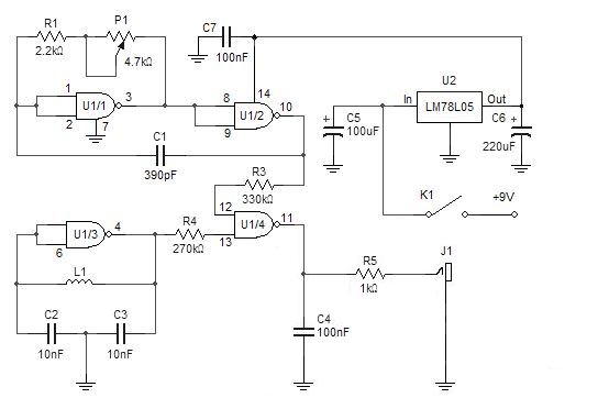
Rangkaian Pendeteksi Logam

Rangkaian Pendeteksi Logam
This simple metal detector requires alone a scattering of apparatus and an evening’s work. Congenital about a cmos4011 IC, is actual able-bodied and versatile. The 250 kHz advertence oscillator is congenital with two gates (U1/1 and U1/2), C1, R1 and P1. The chase oscillator uses alone one aboideau (U1/3), two capacitors and the chase coil. The outputs of the two oscillators are fed to the fourth aboideau acting as a mixer and filtered with C4.

After assembly, affix the headphones and boring about-face P1. The angle will get lower until it disappears. Continuing to circle P1 in the aforementioned administration will account the angle to acceleration again. The point at witch the angle is the everyman and disappears is alleged “zero beat”. If you can not get this aught exhausted abundance for the absolute about-face of P1 you may accept to baddest altered ethics for C1.
Turn P1 abutting to the aught exhausted position, again move the chase braid abreast a brownish object. The accent should change, depending on the admeasurement and ambit of the metal.
Note that this simple detector’s achievement is not commensurable to added avant-garde bartering products. It will alone ascertain about ample brownish altar at a abbreviate distance. Coins and added baby altar will be abundant harder to find!
Here the Beat-frequency Oscillator Simple Metal Detector Schematic Part List :
  • U1: CD4011 (Quad 2-input NAND Gate)
  • U2: LM78L05 (5V Regulator IC)
  • R1: 2.2k 5% resistor
  • R3: 330k 5% resistor
  • R4: 270k 5% resistor
  • R5: 1k 5% resistor
  • C1: 390pF NPO capacitor
  • C2, C3: 10nF
  • C4: 100nF
  • C5: 100uF/16V electrolytic
  • C6: 220uF/16V electrolytic
  • C7: 100nF ceramic
  • P1: 4.7k lin. potentiometer
  • L1: 22cm diameter, 14 turns, AWG 26
  • K1: SPDT toggle switch
  • J1: Headphone jack 1/4 or 1/8 inch

1000 Watt Mosfet Power Inverter

This power inverter circuit will provide a very stable “Square Wave” Output Voltage. Frequency of operation is determined by a pot and is normally set to 60 Hz. Various “off the shelf” transformers can be used. Or Custom wind your own for best results.

Additional MosFets can be paralleled for higher power. It is recommended to Have a “Fuse” in the Power Line and to always have a “Load connected”, while power is being applied. The Fuse should be rated at 32 volts and should be aproximately 10 Amps per 100 watts of output. The Power leads must be heavy enough wire to handle this High Current Draw! appropriate Heat Sinks Should be used on the RFP50N06 Fets. These Fets are rated at 50 Amps and 60 Volts. Other types of Mosfets can be substituted if you wish.
There ARE Limitations! I have had numerous requests for an Inverter for 1000 watts and Even MORE. Sorry I Don’t feel this is Practical. At 1000 Watts and operating from a 12 Volt Source, the Input Current will be close to 100 AMPS. That would Require a HUGH Size of a Primary Wire.

Sensor IC LM35 based Overheat Detector Alarm Switch

Sensor IC LM35 based Overheat Detector Alarm SwitchThis is Overheat Detector Alarm Switch using Temperature Sensor IC LM35 Electronic Suite Diagram, at the heart of this overhead detector (fire alarm) circuit is a precision integrated temperature sensor type LM35 (IC1), which provides an accurately linear and directly proportional output in mV, over the zero to +155 degrees C temperature range. This can be used as part of fire smoke detectors but do not use it as a home fire alarm system.
The LM35 develops an output voltage of 10 mV/K change in measured temperature.
Designed to draw a minimal current of its own,
the LM35 has very low self heating in still air.
Here the output of the LM35 is applied to the non-inverting input of a comparator wired around a CA3130 opamp (IC2). A voltage divider network R3-P1 sets the threshold voltage, at the inverting input of the opamp. The threshold voltage determines the adjustable temperature trip level at which the circuit is activated.
When the measured temperature exceeds the user-defined level, the comparator pulls its output High to approx. 2.2 V causing transistor T1 to be forward biased instantly. T2 is also switched on, supplying the oscillator circuit around IC3 with sufficient voltage to start working. The 555 set up in astable mode directly drives active piezoelectric buzzer Bz1 to raise a loud alert. Components R7, R8 and C4 determine the on/off rhythm of the sounderA transistor based relay driver may be driven off the emitter of T1 (TP1). Similarly, replacing the piezo sounder with a suitable relay allows switching of high-power flashers, sirens or horns working on the AC mains supply.

S:electronicsuite.com

2 Watt FM Transmitter

The circuit is basically a radio frequency (RF) oscillator that operates around 100 MHz. Audio picked up and amplified by the electret microphone is fed into the audio amplifier stage built around the first transistor. Output from the collector is fed into the base of the second transistor where it modulates the resonant frequency of the tank circuit (L1 coil and the trimcap) by varying the junction capacitance of the transistor. Junction capacitance is a function of the potential difference applied to the base of the transistor T2. The tank circuit is connected in a Hartley oscillator circuit.

Components List

R1=220K
R2=4.7K
R3,R4=10K
R5=100ohm
C1,C2=4.7uF Electrolytic
C3,C4=1nF
C5=2-15pF
C6=3.3pF
Q1=BC547C
Q2=BD135
P1=25K
MIC=Electret Condenser Type
P1 act as condenser microphone volume level. For FM, coil will be small. Use thin gauge enamel magnet wire. the diameter of coil will be a couple mm: use ink tube from pen to form, and try 8-12 turns. Small inductance coils make for much guess work.

Stereo FM Transmitter Based BH1417 Chips

This electronic circuit is a latest BH1417 FM Transmitter design from RHOM that includes a lot of features in one small package. It comes with pre-emphasis, limiter so that the music can be transmitted at the same audio level, stereo encoder for stereo transmission, low pass filter that blocks any audio signals above 15KHz to prevent any RF interference, PLL circuit that provides rock solid frequency transmission (no more frequency drift), FM oscillator and RF output buffer.

There are 14 possible transmission frequencies with 200KHz increments that users can select with a 4-DIP switch. Lower band frequencies start from 88.7 up to 89.9 MHz, and upper band frequencies start from 107.7 up to 108.9 MHz.


BH1417 can be supplied with 4 - 6 voltage and consumes only around 30mA, providing 20mW output RF power. BH1417 provides 40dB channel separation which is pretty good, although older BA1404 FM Transmitter chip provides slightly better 45dB channel separation.


BH1417 is only available in SOP22 IC case so this may be an inconvenience for some folks. On the other hand, because the chip is smaller than regular DIP-based ICs it is possible to fit the entire transmitter on a small PCB.

The bad news is that BH1417 requires 7.6MHz crystal oscillator, which is very hard to find. The good news is that you can use 7.68 MHz crystal instead, which is easier to find. In fact our BH1417 transmitter prototype (schematic shown above) uses 7.68 MHz crystal. This has absolutely no effect on stereo encoding process, we have tested it and stereo sound is crystal clear. The transmitted frequency on the other hand will be shifted up by exactly 1MHz (example: 88.1 MHz to 89.1 MHz) which is perfectly fine. The frequencies that are used in this project have been adjusted by 1MHz already so no additional conversion is necessary.

BH1417 chip may also be used a stand alone stereo encoder. The advantage of that is that you have full freedom of using a transmitter & amplifier of your choice. You will still have a pre-emphasis, limiter,stereo encoder and low pass filter in one small package because very few external components are required for these blocks. PIN 5 is MPX output that can be directly connected to an external FM transmitter through a 10uF cap.


Parts List:
1x BH1417 - Stereo PLL Transmitter IC (Case SOP22) (datasheet)
1x 7.68 MHz Crystal
1x MPSA13 - NPN Darlington Transistor
1x 2.5 Turns Variable Coil
1x MV2109 - Varicap Diode
1x 4-DIP Switch
ANT - 30 cm of copper wire

1x 22K Resistor
7x 10K Resistor
1x 5.1K Resistor
2x 3.3K Resistor
1x 100 Ohm Resistor 1x 100uF Capacitor
3x 10uF Capacitor
2x 1uF Capacitor

1x 47nF Capacitor
3x 2.2nF Capacitor
1x 1nF Capacitor
1x 330pF Capacitor
2x 150pF Capacitor
1x 33pF Capacitor
2x 27pF Capacitor
1x 22pF Capacitor
2x 10pF Capacitor

Specifications:
Supply Voltage: 4 - 6V
Transmission Frequency: 87.7 - 88.9MHz, 106.7 - 107.9MHz (200kHz steps)
Output RF Power: 20mW
Audio Frequency: 20 - 15KHz
Separation: 40dB
Power Consumption: 30mA

Frequency Selection / Calibration
Frequency selection is very straight forward. Simply select transmission frequency at which you would like to transmit, set the combination for 4-DIP switch and BH1417 will immediately tune to that frequency. If you can't hear the transmitted audio signal on your FM receiver then re-adjust 2.5 turn variable coil until you can hear the signal. If you have a laboratory power supply you may try to vary the voltage supply from 4 to 6V. While doing that BH1417 will automatically vary the voltage for MV2109 varicap diode making sure that there's no frequency drift.

Share

Twitter Delicious Facebook Digg Stumbleupon Favorites