This is default featured post 1 title

Go to Blogger edit html and find these sentences.Now replace these sentences with your own descriptions.This theme is Bloggerized by Lasantha Bandara - Premiumbloggertemplates.com.

This is default featured post 2 title

Go to Blogger edit html and find these sentences.Now replace these sentences with your own descriptions.This theme is Bloggerized by Lasantha Bandara - Premiumbloggertemplates.com.

This is default featured post 3 title

Go to Blogger edit html and find these sentences.Now replace these sentences with your own descriptions.This theme is Bloggerized by Lasantha Bandara - Premiumbloggertemplates.com.

This is default featured post 4 title

Go to Blogger edit html and find these sentences.Now replace these sentences with your own descriptions.This theme is Bloggerized by Lasantha Bandara - Premiumbloggertemplates.com.

This is default featured post 5 title

Go to Blogger edit html and find these sentences.Now replace these sentences with your own descriptions.This theme is Bloggerized by Lasantha Bandara - Premiumbloggertemplates.com.

Showing posts with label Microphones. Show all posts

Saturday, March 24, 2012

Rangkaian Microphone/Mic FM Wireless

Microphone/Mic FM  Wireless
Skema Rangkaian Microphone/Mic FM Wireless
Microphone/Mic FM Wireless is basically an FM transmitter to low power. FM Wireless Mic circuit you can use it to replace the wireless mic is usually quite expensive price. If you are a fan of electronics, then the series is worth your trying, but its component prices cheaper tool is also very useful. Here is a picture of his series:


List Component of Microphone/Mic Wireless :
 
1 = 10K (brown-black-orange)
R2,R3 = 100K (brown-black-yellow)
R4 = 470 ohm (yellow-violet-brown)
C1,C3 = 4.7pF (4p7), ceramic
C2,C4 = 4.7uF-16V, electrolytic
C5 = 0.001uF (1nF), ceramic
C6 = 470pF, ceramic
Q1,Q2 = 2N2222, NPN transistor
L1 = 1uH, variable inductor
Mic = Electret mike, 2 wires


Q1 amplifies the input signal via C4 from the electret microphone. Q2 acts as an oscillator and the signal coming off C2 is fed onto the base of Q2. L1/C1 is a so called ‘tank’ circuit and operates in the 88-105MHz band on your regular AM/FM radio dial.
L1 is a 1uH variable inductor coil to be able to tune it a little bit, and the range of 1uH is approximate. The antenna can be as simple as a 8″ (21cm) piece of wire of any kind.

Wednesday, March 21, 2012

Rangkaian Audio Mixer 3 Input

Many audio mixer circuits have been published but this this very simple audio mixer circuit uses only one transistor. The base emitter junction of the transistor is biased by the diodes D1 and D2.The signals to be mixed are directly coupled to the base of Transistor. Each input lines are current limited by using a 10k Potensiometer . With the used component values the collector current is around 1mA.
Audio MixerSkema Rangkaian Audio Mixer 3 Input

Notice:
  • The circuit can be assembled on a Vero board.
  • The circuit can be powered from 9-25V DC.
  • of each channel can be set using Variable resistor 10k

Transistors in the following series is enabled as a source of constant flow. By providing input audio signal on the emitter, the voltage on the emitter will fluctuate, which will cause the collector voltage also fluctuates. The amount of frequency fluctuation is comparable with the frequency of the incoming audio signal.

Friday, March 16, 2012

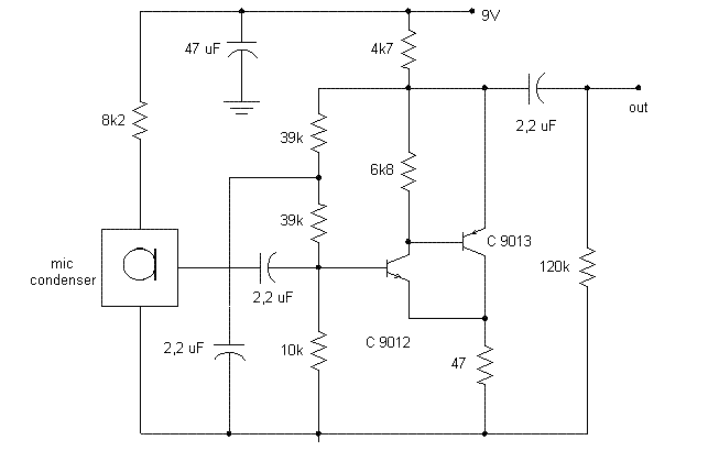
Circuits of audio pre-Amp mic

A microphone preamp is a preamplifier used to amplify a microphone's low output voltage to a stronger, more usable level. A microphone preamp must provide stable gain for small signals without being sensitive to induced noise from cabling and without distorting large amplitude signals. Most microphones must be used in conjunction with a microphone preamp to function properly.

Simple audio Pre-Amp mic

This circuits use infront an RF oscilator to make an RF transmitter that is very sensitive to sound

Share

Twitter Delicious Facebook Digg Stumbleupon Favorites